The Chinese VHF 500W Kit
People are talking about this super cheap VHF 500W amplifier kits from China, for $35 it comes with the PCB and all components including the LPF, even on-board couplers for SWR! Pretty good deal, isn't it?

Is it?
Here's the catch, or maybe I should say: "Here are the catches."?
First of all, it is a very "simple" design, trying to squeeze a pair of 600W transistors onto board that was originally designed for 170W FM band. It has no thermal compensation to lower the bias in when the amp gets hot, and speaking of bias, there is only one potentiometer for the two MRF300s to share, making adjusting IDQ individually impossible. There is no bias switching circuitry either, unlike other popular amp designs that only supply bias when TX, on this amp the bias will be always on, resulting in warmer transistors.
Other things to keep in mind:
- The bias potentiometer, as the schematics suggests, is placed on the upper side of the voltage divider, which means the bias/IDQ will increase when turned anticlockwise, which is kind of not intuitive and sometime dangerous. The potentiometer is not a multiturn type so that the bias/IDQ adjusting is very touchy, turning for half a circle will give you more than 1A of difference.
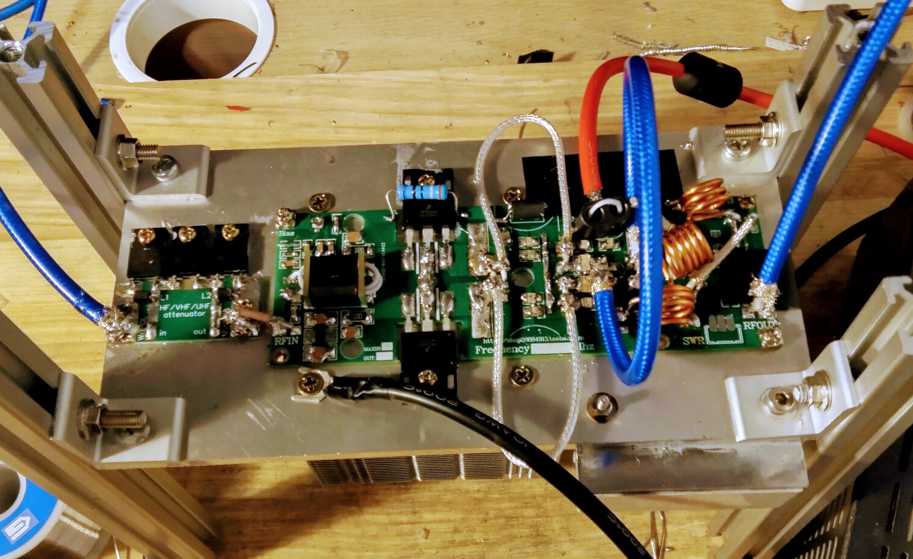
- The kit came with no assemble instructions at all, I was able to obtain higher resolution pictures of the finished board and schematics, but that's all, you are basically on your own building this amp.
- The provided components are not entirely in accord with the information shown on the picture and schematics, most of them are not even labeled, a capacitance meter is a must.
- The output impedance match, which is key for the output power, is not quite right with the provided parts. I put together two sets following the information provided by the seller, which includes cutting the unknown white coax in half to construct a TLT, I was only able to get 150-200W output.
- The provided enameled wire may be too thin for 500W output, I'd suggest at least 2mm diameter.
Yes, the $35 price is vey tempting, but it all come down to how much time you have to tune it and how much money you would be willing to spend on getting additional parts. Alternatives includes the famous EB104's "everything but transistors" assembled MRF300 board for $80, as far as LPF, it would be an easy homebrew project.
Anyway, the followings are things I changed to make it work as advertised, after trying four sets of kits and blowing two pairs of MRF300s:
- Input transformer: I used 1:4 (1:2 turning ratio) instead of 1:9 (1:3 turning ratio) that the seller suggested on the picture he sent. 1:4 seems to have better frequency response on this board.
- Output impedance matching: For capacitors I paralleled two 300pF MLCCs (ATC100B) instead of 100pF. For TLT I used two 12cm of 12.5ohm PTFE coax, I am not a RF expert and don't know how to calculate the right length and capacitance, these are the result of try-and-error. For balun it is 18cm of RG-142.
- LPF: In addition to thicker wire, two short lengths of 12.5ohm coax serve as capacitors, they tolerate high voltage and can be trimmed to optimized value, incorporating the existing capacitance that the PCB has:


留言
張貼留言